Big foot assignment
Innovations assignment
link: http://slidespeech.com/s/5ZQYEhUqen/
Arduino TutorialSCHEMATIC:
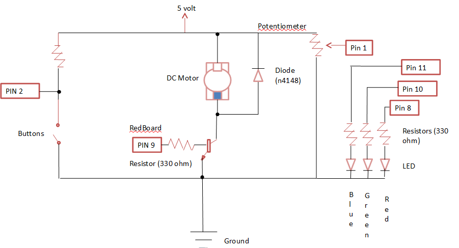
INSTRUCTIONS:
1. First take a wire and connect it to the five volt on the Red Board and to a positive part on the Breadboard. Also take a wire and connect it to the ground on the Red Board and to a negative part on the Breadboard. 2. Second connect a wire from j2 on the Breadboard to the pin 9 on the Red Board. 3. Next connect a wire on the positive part to a7. Also connect a wire to a negative part to e1. 4. After take the diode and place the diode on b7 and b11. 5. With the motor take the red wire and place it on e7 and the black wire on e11. 6. Place the transistor, front side facing the right, on a1, a2, a3. 7. Next place a 330 ohm resistor with the orange side on e2 and the other side on g2. Now place a wire on e3 and e11. 8. Take a wire and place it in Pin 2 to b14. Then take a wire and attach it to a negative part on the Breadboard to a12. Next a 10k ohm resistor and place the brown side on a14 and the other side on a positive part on Breadboard. 9. With the button place in on c14, c12 with the other studs following. 10. Now place the potentiometer on b 17, 18, and 19 (with the 3 and 1 on the potentiometer facing left. 11. Next take a wire and place it on a positive part and e17. Also take a wire and place it on a negative part and e19. 12. Take a wire and place it on Pin 1 and on e18. 13. Now with the RGB LED, place it starting with the red side and place it on a24 with the rest of the sides following down. 14. With three 303 ohm resistors, place them, with the double orange side facing left, on e24 to g24, e26 to g26, and e27, to g27. 15. Have a wire connected to h24 to Pin 8, a wire to h26 to Pin 10, and a wire to h27 to Pin 11. 16. Lastly take a wire and attach it to e25 and a negative part on the Bread Board. Source code:
When creating code that would make a button turn on a motor, I came across on the Arduino examples a code that just had the motor turn when connected. I just added the button into the code in order to make it mine. With my RGB LED and potentiometer coding, it was found off a website post that in general did what I wanted. As a change, I created a different color scheme for the RGB LED. Troubleshooting Guide:
|
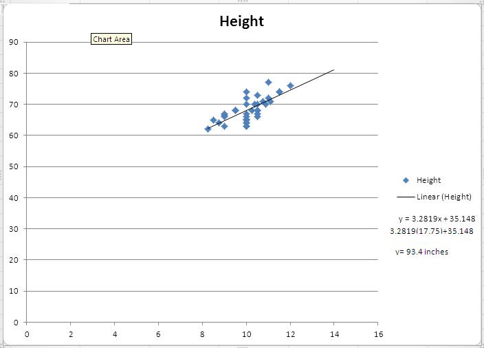
For my research, i used data from class periods one and two. To clean my data, I deleted repeats and outliers, fixed typos, and took out units. I then filtered the data by placing the data from A to Z by first name. Using my finalized data, I then created a graph. With this graph I was able to find a line of best fit and create a equation to calculate the average height of BigFoot by using his feet size.
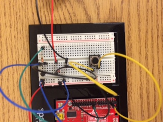
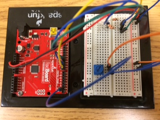
Guide Pictures: (pictures are not matched with instructions.)
Feedback: When receiving, the main thing that i had to fix was the fact the coding and wiring didn't match together. Also that I had to be more specific when explaining the locations of the wiring.
Coding: int LEDGreen=8; int LEDBlue=10; int LEDRed=11; const int buttonPin = 2; const int motorPin = 9; int buttonState = 0; int sensorPin=1; int val; void setup(){ pinMode(motorPin, OUTPUT); pinMode(buttonPin, INPUT); Serial.begin(9600); pinMode(LEDRed,OUTPUT); pinMode(LEDGreen,OUTPUT); pinMode(LEDBlue,OUTPUT); } void loop() { val=map(analogRead(sensorPin),0,1024,0,900); Serial.println(val); if (val<150) { analogWrite(LEDRed,0); analogWrite(LEDBlue,0); analogWrite(LEDGreen,255); } else if (val<300) { analogWrite(LEDRed,map(val,150,300,0,255)); analogWrite(LEDBlue,map(val,150,300,255,0)); analogWrite(LEDGreen,255); } else if (val<450) { analogWrite(LEDRed,255); analogWrite(LEDBlue,0); analogWrite(LEDGreen,147); } else if (val<600) { analogWrite(LEDRed,255); analogWrite(LEDBlue,map(val,450,600,0,255)); analogWrite(LEDGreen,map(val,450,600,255,0)); } else if (val<750) { analogWrite(LEDRed,147); analogWrite(LEDBlue,255); analogWrite(LEDGreen,0); } else if (val<900) { analogWrite(LEDRed,map(val,750,900,255,0)); analogWrite(LEDBlue,255); analogWrite(LEDGreen,map(val,750,900,0,255)); } delay(20); buttonState = digitalRead(buttonPin); if (buttonState == LOW) { digitalWrite(motorPin, HIGH); } else { digitalWrite(motorPin, LOW); } } |
EGG crumple zone project
IDENTIFYING THE PROBLEM: In order to protect an egg from a fall water bottle, our group will need to use a crumple zone.
IDEAS:
CONSTRAINTS:
CRITERIA:
RESEARCH:
IDEAS:
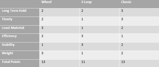
- wheel model
- three loops connected
- classic spring
- mini springs
- crumpled piece of paper
- pyramid
CONSTRAINTS:
- Has to be made out of paper and staples
- Has to absorb the impact
- 2" x 2" x 2" to 4"x4"x4" cube size limit for the crump
CRITERIA:
- Should be lightweight
- Should use as least material possible
- Should be able to make in timely manner
- Should hold together long term
- Should be stable/balanced
- Should be efficient
RESEARCH:
- Empirical: through empirical research, our group observed that the classic spring model absorbed impact better than the other models; the three loop and the wheel models were nearly the same while the others failed. We also observed that the three loop model was the most stable with the classic spring at close second, the the other models were not stable.
- Theoretical: through theoretical research, we knew that sense the models used different amounts of paper, we would have to incorporate that factor in our decision to picking a model.
Possible Solutions:
Through Empirical tests, it was decided we would continue with:
Through Empirical tests, it was decided we would continue with:
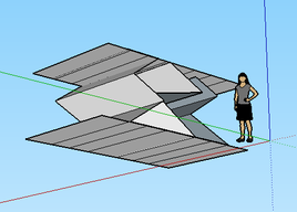
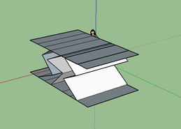
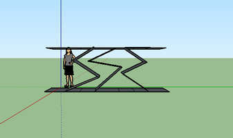
- Wheel Model: consisting of a cylinder shaped model with a spring in it stretching from top to bottom.
- Three Loop Model: consisting of three teardrop shaped pieces of paper stapled together
- Classic Model: consisting of three springs attached to a top and bottom piece of paper
IDEA MATRIX:
Sketchup Model:
|
|
|
SUMMARY:
In conclusion, it was determined that the classic crumple zone would be chosen as the solution. As for backup, it was decided that the wheel model would hold that position. As for a graphical model, I will be using a technical sketch for the classic spring model.
In conclusion, it was determined that the classic crumple zone would be chosen as the solution. As for backup, it was decided that the wheel model would hold that position. As for a graphical model, I will be using a technical sketch for the classic spring model.
Re-Design:
After seeing the drop tests for the different crumple zone models, our main analysis was that springs didn't work at all! We also found that the cone shaped models worked the best. So rather than fixing our spring model that would never work, we instead strapped the idea and made our own cone shaped innovation. This model consists of a center piece cone with support wings on the side.
After seeing the drop tests for the different crumple zone models, our main analysis was that springs didn't work at all! We also found that the cone shaped models worked the best. So rather than fixing our spring model that would never work, we instead strapped the idea and made our own cone shaped innovation. This model consists of a center piece cone with support wings on the side.
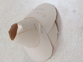
Prompt
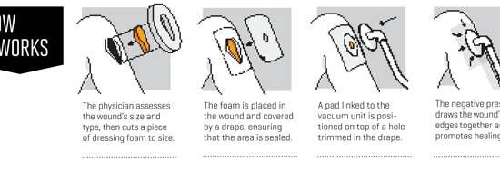
By using this device, medical workers could save more lives that are severely wounded from accidents such as car crashes, falls, job accidents etc. This device would also allow for quicker healing and save medical workers more time for doing other things rather than caring for wounded.
